Our Services
Table Of Contents
After over 25 years in the industry, GP Technologies has been exposed to and has provided solutions to a wide range of challenges. Please see below for a list of the most common issues we help customers overcome.
Common Issues
1. Difficulties In Starting Motor
2. Induction Motors Dropping Out
3. Protective Nuisance Tripping
4. Power Factor Penalties
5. Fuses Randomly Blowing (without a fault)
6. High Arc Flash Incident
Professional Services
1. Engineering Analysis – Summary – Full
2. Engineering Design – Summary – Full
3. Project Management – Summary – Full
4. Protective Relay Testing – Summary – Full
5. Terotechnology Services – Summary – Full
6. ETAP System Integrator – Full
Interactive Module
Click Here to view an interactive module showing a full list of our services and a number of our featured projects.
Professional Services
GP Technologies is an industry leading electrical engineering firm supplying specialized power system engineering services for industrial and utility customers within the oil & gas, mining, petrochemicals, power generation, pulp & paper, water & wastewater, and municipal sectors. Our main services include engineering analysis, engineering design, project management, protective relay testing, and terotechnology.

Engineering Analysis
Specialized engineering analysis utilizing a multitude of industry-accepted software packages, including ETAP, SKM, PSS/e, ATP-EMTP, ASPEN, MATHCAD and MATLAB.

Engineering Design
Engineering design of all aspects of low, medium and high voltage power systems, protection, control and automation systems.

Project Management
Complete management of small to medium sized (<$20 million) projects, from project development through design, procurement, construction/commissioning and closeout.

Protective Relay Testing
While GP Technologies is not a field service company, we provide commissioning services for testing of specialized protection and control schemes, generally from in-house design.

Terotechnology Services
Terotechnology is the practice of optimal maintenance of assets. GP Technologies provides specialized Terotechnology Services utilizing proprietary reliability modeling software and failure mode data.
More
GP Technologies and seen and solved a wide array of challenges facing our customer’s and their facilities. Please see below for a list of the most common issues we help customers overcome.
Common Issues
1. Difficulties in Starting Motor
Reason: Protection is Not Optimal
Background
Modern motor protection utilizes a thermal model, the purpose of which is to continuously update a numeric thermal capacity analogous to the heat within the rotor and stator. Once this thermal capacity reaches 100% of the motor thermal withstand, it will trip the motor.
Issue
Where thermal element settings do not adequately predict the heat within a motor, the motor may be tripped off unnecessarily or will operate above its rated temperature rise, both of which may negatively affect availability to the process.
Solution
In order to optimally set motor thermal protection (overload pickup, acceleration factors, time constants), GP Technologies conducts time-domain analysis to predict probable acceleration times for unloaded/loaded starts, and the associated thermal capacities used. Settings are adjusted to achieve minimum process requirements (time between starts) and to prevent nuisance operation.
Diagram
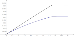
The above image is the calculated heating during a high inertia motor start (starting time approximately 18 seconds). The blue line represents the actual heat in the motor, while the black line is the thermal capacity used on the start. Where these curves diverge, it is indicative of setpoints that do not produce an accurate analogue of motor heat.
Reason: Source Impedance Is Too High
Background
The source impedance of an induction motor needs to be sufficiently low enough to prevent the voltage at the motor terminal from sagging to a prohibitive level.
Issue
The torque developed by an induction motor is proportional to the square of the applied voltage. If the source impedance is too high, the voltage sag resulting from the near locked rotor current flow can reduce torque to at or below the required torque of the load. When this occurs, the motor may have a significantly prolonged start (producing thermal stress), or in some circumstances may stall the motor altogether.
Solution
For new designs, it is critical that a static power flow calculation is conducted to identify the magnitude of voltage sag using locked rotor impedance. There are limited solutions to this problem in an existing system. That said, the mitigation for this issue includes either adjusting upstream fixed taps to maintain a minimum steady state voltage of 101% to 103%, or adding additional reactive compensation to the bus.
Diagram
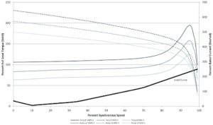
The above image shows a torque-speed and current-speed curve of a typical induction motor. The blue arrow illustrates the reduction in available torque as the stator voltage is reduced. If the voltage sag is large enough, the resultant decrease in available torque may risk stalling the motor.
2. Induction Motors Dropping Out
Reason: Source Power Quality Issues
Background
Faults in an electrical system reduce the line voltage based on the source and fault impedances. In weak systems, even low magnitude faults can depress the voltage below the minimum contactor holding voltage of motor starters.
Issue
When a fault occurs on weak systems, the resultant voltage sag may drop out multiple motors within the system. As it is usually a systemic issue, this typically causes a complete loss of the process.
Solution
As both the fault tolerance and the system impedances cannot easily be changed, there is no easy solution to holding the bus voltage. Stored energy (such as capacitors or batteries) are also not useful in maintaining the voltage during fault conditions, the only solution to this is to allow the motor to attempt to ride through the fault event. This requires two key aspects: 1. The motor and load train must maintain stability, and 2. The contactor coil must remain energized. For the first consideration, this is often not trivial as the loss of voltage means almost complete loss of driving torque, which depending on the type of load, may trip the system in a very short amount of time. For the second consideration, an alternate voltage source (e.g. auxiliary DC or UPS) is usually used. This also creates another risk, however, as the motor is now susceptible to out-of-phase conditions resulting from upstream reclosing. A properly designed motor protection and control system addressed both of these risks, facilitating a system better able to maintain process continuity under fault conditions.
Diagram
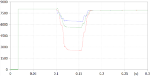
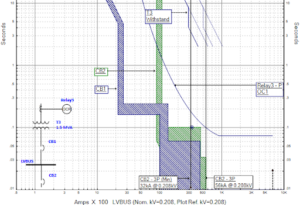
The above image is a simulation of a 3.0Ω LLG fault within a 4.16kV distribution system.
Reason: Transformer Energization Inrush or Sympathetic Inrush
Background
During energization of a transformer (or multiple transformers in parallel), significant inrush current may flow as a result of the highly non-linear relationship between magnetic field strength and magnetic flux density. This large inrush current (which can approach orders of magnitude similar to fault current) can produce considerable voltage sags.
Issue
The voltage sags developed within a power system resulting from transformer inrush can be quite large and may last for as long as several seconds. This long and pronounced reduction in bus voltage can cause the loss of process loads, specifically induction motors.
Solution
The mitigation of this issue is very similar, and in most cases identical, as that for bus fault tolerance of motor contactors.
Diagram
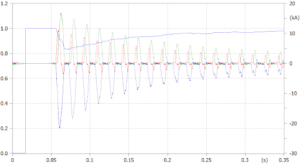
The above image shows the simulated energization of a 15MVA transformer.
3. Protective Device Nuisance Tripping
Reason: Miscoordination of Protective Devices
Background
In order to achieve acceptable selective coordination of overcurrent protective devices, a minimum Coordination Time Interval (CTI) is required within the probably fault region, as outlined in IEEE Std 242 (IEEE Buff Book).
Issue
When a fault occurs on weak systems, the resultant voltage sag may drop out multiple motors within the system. As it is usually a systemic issue, this typically causes a complete loss of the process.
Solution
A balanced approach of overcurrent element setpoint development is taken. The primary goal of most systems is to ensure process continuity. However, where selective coordination is achieved, fast clearing time is sacrificed, which can put personnel safety at risk. By quantifying incident energy risks, as well as bus financial criticality, a right balance can be struck between safety and continuity.
Diagram
The above plot shows an example Time-Current Characteristic (TCC) Curve illustrating clear miscoordination of all protective devices within the probable fault range (32kA to 56kA).
4. Power Factor Penalties
Reason: Miscoordination of Protective Devices
Background
Most industrial electrical distribution system loads are comprised of induction motors. Given that induction motors generally operate with a power factor of between 0.86 and 0.92, the facility as a whole will operate at or below this range at the point of utility service (usually referred to as the point of common coupling, or PCC)
Issue
Utilities do not want to supply customers with their required reactive power as, among other things, it limits the ability to transfer real power and requires increased ratings of major electrical equipment. Utilities also cannot readily charge customers for supplying them reactive power. As such, most if not all utilities, provide separate power factor charges in addition to the billing of real energy.
Solution
There are several ways which an industrial electrical distribution system may increase its power factor at the PCC. These include the use of synchronous machines in place of induction machines, shunt capacitor or filter banks, and the use of voltage source variable frequency drives.
Formula
![]()
The above formula is an example (from the Alberta Electric System Operator) of a power factor penalty calculation.
5. Fuses Randomly Blowing (without a fault)
Reason: Misapplication of Shunt Capacitor / Filter Banks
Background
Shunt capacitor and filter banks are used very often within industrial power systems to assist in supporting bus voltages, providing reactive compensation for power factor purposes, and to limit harmonic current penetration into upstream systems.
Issue
It is very common to have shunt capacitors or even filter banks applied to a low or medium voltage power system without conducting any type of frequency domain analysis. If a shunt capacitor or filter is applied to a system where a characteristic (resonant) frequency is close to harmonic orders of the system, non-linear loads may excite the shunt device at this mode, producing large current flows and voltage drops across the equipment.
Solution
The solution to these resonance issues is to identify them in the first place. GP Technologies uses EMTP software to develop comprehensive system models with which to conduct frequency-domain analyses. A frequency sweep of the system is conducted, and the resonant modes are identified. Once identified, mitigative action (such as modifying the characteristic frequency of a filter, or removing shunt capacitance) can be taken to move the resonant frequency away from known harmonic sources.
Diagram
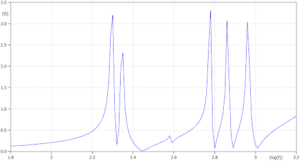
The image above is from a frequency-domain analysis of a large industrial power system with multiple de-tuned filter banks.
6. High Arc Flash Incident Energy
Reason: High Arc Flash Incident Energy
Background
All electrical distribution systems greater than 208V and 208V systems with an available bolted fault current above 2kA have arc flash hazard risk.
Issue
High arc flash incident energies not only result in unnecessary personnel safety risk, but also can constrain operation or maintenance activities by completely preventing the local operation of breakers / contactors. In addition, there is an increased risk of nuisance tripping where personnel are required to don sight and touch-inhibiting PPE that would otherwise be unnecessary.
Solution
There are many solutions to reducing arc flash hazard risk. The first is to remove personnel from the arc flash boundary to begin with. Where this is not possible (i.e. remote operation is not available), the next step is to reduce clearing time. This can be done in many ways from a protection standpoint (zone interlocking, overlapping differential zones, manual maintenance mode selectors, tightening coordination time intervals, etc.), but also requires that an upstream isolation device (circuit breaker) is available. This is usually the biggest issue for the problematic areas in power distribution systems (first bus downstream of transformers). Generally, a combination of things are done, first by retrofitting existing isolation devices to be electrically operable. Next, by upgrading protective relaying so that communication-assisted protection schemes may be utilized. Following these relatively inexpensive options, isolation devices and switchgear is typically upgraded.
The other important note about incident energy is the compounding uncertainty in most arc flash study results. While there is a consensus standard that outlines the recommended guidelines for conducting the analysis (IEEE Std 1584.1-2022), the possible variance in approach of one engineer to another may result in significantly different numbers. GP Technologies approaches this issue by conducting One-At-A-Time sensitivity analyses of the dependent variables so as to quantify the calculation uncertainty.
Diagram
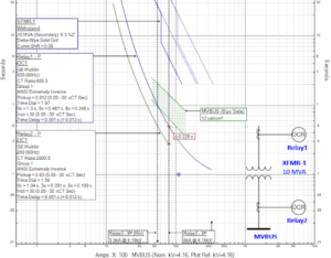
The above image is a Time-Current Characteristic (TCC) Curve of a simple 4.16kV system with two relays. The green hatched area is the constant incident energy curve (per IEEE Std 1584-2018) for 12.0 cal/cm2. It is GP Technologies’ general practice to maintain incident energies below this value as there is a step change in the required PPE above 12.0 cal/cm2 (per Table 3 of CSA Z462-21)


WHY GP TECH?
GP Technologies has successfully completed more than 1900 projects for 140+ different clients, with 0 lost time hours. We take pride in our work and would be proud to help you through your next challenge.
25+ Years Of Experience
Committed To Value
Power System Experts
Provides Service North American Wide
Engineering Analysis, Design, And Project Management
Protective Relay Testing and Terotechnology
Professional Services
1. Engineering Design
|
A |
Protective Relaying Upgrades |
|
|
A1 |
Induction Motor and Drive Protection up to 20,000HP |
|
|
A2 |
Distribution and Transmission Line Protection up to 240kV |
|
|
A3 |
Transformer and Reactor Protection up to 450MVA |
|
|
A4 |
Bus Protection |
|
|
A5 |
Synchronous Motor Protection up to 15,000HP |
|
|
A6 |
Generator Protection up to 450MVA (Steam and Gas Turbine) |
|
|
|
|
|
|
B |
Electrical Infrastructure Design, Execution and Commissioning |
|
|
B1 |
Low and Medium Voltage Switchgear Upgrades |
|
|
B2 |
Electrical Service Building (E-House) Design |
|
|
B3 |
OT Network Design and Programming |
|
|
B4 |
Large Synchronous Motor Design and Control |
|
|
B5 |
Variable Frequency Drive Installations up to 20,000HP |
|
|
B6 |
Critical DC Distribution System Design |
|
|
B7 |
Emergency Power Topology Design |
|
|
B8 |
Surge Protection Design |
|
|
B9 |
IPS Bus and Substation Structure Design |
|
|
B10 |
Overhead Line Design up to 72kV |
|
|
B11 |
Large Ampacity Busswork up to 30,000A |
|
|
B12 |
Hazardous Area Classification |
|
|
B13 |
Instrument / Analyzer (Safety Critical, DCS, SIS) System Design |
|
|
B14 |
Emergency Generation System Design (Diesel / Gas Recip) |
|
|
B15 |
Steam & Gas Turbine Generator Protection and Control Design |
|
|
B16 |
Grounding Resistor / Transformer Design |
|
|
B17 |
Combined Heat and Power (Cogen) System Design |
|
|
B18 |
Substation Ground Grid Design |
|
|
B19 |
Reactor and Harmonic Filter Design |
|
|
B20 |
Serial/Ethernet Radio Installations |
|
|
B21 |
Distribution System Customer Servicing |
|
|
B22 |
Portable / Unit Substation Design |
|
|
|
|
|
|
C |
Protection and Control Scheme Design |
|
|
C1 |
Bus Transfer Schemes |
|
|
C2 |
Undervoltage / Underfrequency Load Shedding |
|
|
C3 |
Zone Interlocking |
|
|
C4 |
Breaker Failure |
|
|
C5 |
Voltage Regulation Coordination (SVR, OLTC, etc.) |
|
|
C6 |
Distribution Line Reclosing |
|
|
C7 |
Communication-Assisted Protection Schemes |
|
|
C8 |
Synchronization Schemes |
|
|
C9 |
Sequential Motor Restart Schemes |
|
|
C10 |
Anti-Islanding Protection Schemes |
|
|
|
|
|
|
D |
OT Network Design and Programming |
|
|
D1 |
Network Topology Design |
|
|
D2 |
IEEE 1588 PTP System Implementation |
|
|
D3 |
Substation Automation Controller Programming (SEL RTAC, GE D400/G500) |
|
|
D4 |
Phasor Measurement Unit (Synchrophasors) System Implementation |
|
|
D5 |
SCADA Server and Firewall Programming – ISO Interface |
|
|
D6 |
SCADA Server and Firewall Programming – Business Network Interface |
|
|
D7 |
HMI System Development |
|
|
D8 |
Software-Defined Network Programming |
|
|
D9 |
PLC Programming |
|
|
|
|
|
|
E |
Project Management / Development and Process Support |
|
|
E1 |
Shutdown Planning and Coordination |
|
|
E2 |
Construction / Commissioning Support |
|
|
E3 |
Front-End Engineering Design (FEED) |
|
|
E4 |
Total Installed Cost Estimations |
|
|
E5 |
Electrical Hazard and Operability (HAZOP) Analysis |
|
|
E6 |
Failure Mode and Effects Analysis |
|
|
E7 |
Equipment End-of-Life Assessments |
|
|
E8 |
Relay / Protection Scheme Testing |
|
|
E9 |
Witness Testing |
|
|
E10 |
Power Quality Measurements |
|
|
E11 |
Major Equipment Specification and Technical Bid Evaluation |
|
2. Engineering Analysis
|
F |
STEADY-STATE (PHASOR DOMAIN) |
|
|
F1 |
Balanced Short Circuit (ANSI C37) |
|
|
F2 |
Unbalanced Short Circuit (Symmetrical Component Analysis) |
|
|
F3 |
Fault Voltage Profile (Steady-State) |
|
|
F4 |
Power Flow |
|
|
F5 |
Static Motor Starting (Locked Rotor Power Flow) |
|
|
F6 |
AC Arc Flash Hazard Analysis |
|
|
F7 |
DC Arc Flash Hazard Analysis |
|
|
|
|
|
|
G |
TIME DOMAIN |
|
|
G1 |
Time-Variant Short Circuit |
|
|
Bulk Power System |
||
|
G2 |
Short Term Voltage Stability |
|
|
G3 |
Long Term Voltage Stability |
|
|
G4 |
Black Start Simulation |
|
|
G5 |
Underfrequency Load Shedding |
|
|
G6 |
Undervoltage Load Shedding |
|
|
G7 |
Generation Islanding Simulation |
|
|
Rotating Machines |
||
|
G8 |
Generator Rotor Angle Stability / CCT Analysis |
|
|
G9 |
Motor Dynamic Acceleration |
|
|
G10 |
Simultaneous and Sequential Reacceleration |
|
|
G11 |
Motor High-Speed Bus Transfer Dynamics |
|
|
G12 |
Induction and Synchronous Machine Ride-Through |
|
|
G13 |
Sub-Synchronous Resonance |
|
|
G14 |
Load Rejection Response |
|
|
Transformers |
||
|
G15 |
Power Transformer Inrush |
|
|
G16 |
Ferroresonance Simulation |
|
|
Conductor / Switchgear Assemblies |
||
|
G17 |
Switching Surges (Deterministic and Probabilistic) |
|
|
G18 |
Transient Recovery Voltage |
|
|
G19 |
Surge Arrester Modeling |
|
|
G20 |
Sheath Voltage Rise Modeling |
|
|
G21 |
Current Limiting Overvoltage Coordination |
|
|
G22 |
Termporary Overvoltage |
|
|
|
|
|
|
H |
FINITE ELEMENT ANALYSIS |
|
|
H1 |
Ground Grid Modeling |
|
|
|
|
|
|
I |
PROTECTIVE DEVICE COORDINATION |
|
|
I1 |
Time-Overcurrent Coordination |
|
|
I2 |
Voltage-Restrained Overcurrent Coordination |
|
|
I3 |
Time-Undervoltage Coordination |
|
|
I4 |
Asymmetrical & Time-Variant Element Response |
|
|
I5 |
MCCB & Current Limiting Device Selectivity |
|
|
|
|
|
|
J |
HARMONIC (FREQUENCY DOMAIN) |
|
|
J1 |
Harmonic Response Modeling |
|
|
J2 |
Harmonic Indices (THD, TDD, I*T) Evaluation |
|
|
J3 |
Transformer Phase Shift and Filter Modeling |
|
|
J4 |
Harmonic Power Flow |
|
|
|
|
|
|
K |
PROBIBILITY AND STATISTICAL ANALYSIS |
|
|
K1 |
One Factor at a Time (OFAT) Variable Sensitivity Analysis |
|
|
K2 |
Lightning Surge Analysis |
|
|
K3 |
Insulation Coordination |
|
|
K4 |
Reliability Assessment (CIGRE 13-06, IEEE Std 3006) |
|
|
K5 |
Seasonal Load and Voltage Profile Statistics |
|
|
|
|
|
|
L |
CALCULATIONS |
|
|
L1 |
Equivalent Circuit Parameters |
|
|
L2 |
CT Saturation – INST/RMS Secondary Current |
|
|
L3 |
CT Saturation – Time to Saturate |
|
|
L4 |
Temporary Ground Assembly Sizing |
|
|
L5 |
Conductor Current Carrying Capacity Calculation |
|
|
L6 |
Motor Thermal Model Calculation |
|
|
L7 |
Distributed Capacitance (Charging Current) Calculation |
|
|
L8 |
ANSI 21, 64TN, 78, 81R Element Calculation |
|
|
L9 |
Cable Pull Tension Calculation |
|
|
L10 |
Induced Potential Rise Calculation |
|
|
M |
DISTRIBUTED ENERGY RESOURCES (Solar PV, BESS, etc.) INTERCONNECTION STUDIES |
|
|
M1 |
Anti-Islanding Element (Time-Domain) Analysis |
|
|
M2 |
Temporary Overvoltage (Phasor-Domain and Time-Domain) Analysis |
|
|
M3 |
Transient Recovery Voltage Analysis |
|
|
M4 |
Overcurrent Element Desensitization Calculations |
|
Contact Links
Phone: (780) 440-3344
Email: [email protected]
Located: 2nd floor of 16060 – 114 Avenue, Edmonton, Alberta, T6E 5X4
Serving: North America